Showing posts with label Musculo-Skeletal MRI Protocols. Show all posts

Foot-Toes Infection / Tumor MRI protocols

  • Axial T1
  • Axial T2
  • Axial STIR
  • Coronal T1
  • Coronal STIR
  • Sagittal STIR
Optional Post Gad 
  • Axial T1 Fat Sat
  • Coronal T1 Fat Sat
The routine examination is performed with the patient lying supine with the foot positioned in an extremity coil. Alternatively the forefoot may be imaged in the prone position with the toes in an extremity coil. The foot is normally placed in the neutral position but may be plantar flexed if there is concern regarding the tendons.

T1    Anatomically detailed with high resolution. Sensitive for bone marrow changes, however may miss bone marrow edema in the smaller phalanges.

T2    Less sensitive to bone marrow edema, especially when fast spin echo sequences are employed due the bright signal of edema blending with the bright signal of the fatty bone marrow. T2 with fat saturation avoids this problem, but the foot may difficult to obtain a uniform fat saturation. Inhomogeneous fat saturation may lead to diagnostic error.

STIR Very sensitive to bone marrow edema changes. Uniform fat saturation easily obtained.
Intavenous gadolinium is generally not needed on a routine basis.  It may improve sensitivity for small abscesses or sinus tracts.


-->

Thumb MRI Protocol


  • Axial T1
  • Axial PD Fat sat
  • Coronal T1 
  • Coronal T2
  • Coronal PD Fat sat
  • Sagital STIR
  • Sagital PD fat sat
 "Thumb MRI Protocol"
Thumb MRI imaging planes

-->

MRI of the six labral zones of the glenoid labrum


MRI of the six labral zones of the glenoid labrum
Fat suppressed oblique sagittal T1 weighted MR arthrogram image, demonstrating the six labral zones of the glenoid labrum.

Appearance of Knee joint Cartilage Lesions on MRI

The appearance of cartilage lesions on MRI depends on whether they are degenerative or posttraumatic in cause. Early degenerative cartilage lesions in patients with osteoarthritis appear as fibrillation, pitting, and fissuring of the articular surface. As the disease progresses, a focal partial-thickness cartilage defect with obtuse margins develops in the area of cartilage degeneration . In patients with advanced osteoarthritis, multiple partial-thickness and full-thickness cartilage defects, cartilage delamination, and diffuse cartilage thinning involving opposing articular surfaces of the knee joint are typically present .
Degenerative cartilage lesions can be associated with changes in the underlying subchondral bone marrow. The bone marrow edema pattern, which consists of ill-defined areas of high T2 signal, is the most common finding and can be seen adjacent to 5–54% of cartilage lesions depending on their size and depth . Although the high T2 signal within the subchondral bone marrow was originally thought to represent marrow edema, studies have shown that these areas of signal abnormality actually correspond to areas of marrow necrosis, fibrosis, and trabecular disorganization on histologic analysis . The bone marrow edema pattern may be a particularly important secondary finding in patients with degenerative cartilage lesions because its presence has been correlated with pain and disease progression in some research studies. In patients with advanced osteoarthritis, high T2-signal cysts or low T1- and T2-signal sclerosis can be seen within the subchondral bone marrow adjacent to deep partial-thickness and full-thickness cartilage defects.
Posttraumatic cartilage lesions within the knee joint are the result of shearing, tangential, or rotational forces on the articular surface, and their appearance on MRI depends on the mechanism of injury. Shearing forces secondary to injuries, such as transient patellar dislocation, typically result in deep partial-thickness or full-thickness cartilage defects with acutely angulated margins that may also involve the underlying subchondral bone. Linear cartilage flap tears and delamination injuries at the junction between the articular cartilage and subchondral bone also can occur . Cartilage shearing injuries are commonly unstable and result in partially or completely displaced cartilaginous or osteochondral fragments with associated intraarticular loose bodies .
Tangential and rotational forces on articular cartilage secondary to injuries, such as anterior cruciate ligament tear, typically result in osteochondral impaction injuries. These impaction injuries manifest as areas of high T2-signal subchondral bone marrow edema within the anterior lateral femoral condyle and posterior tibial plateau with occasional depression of the articular surface and trabecular fracture lines . The articular cartilage overlying areas of bone marrow edema usually appears normal on MRI and even at arthroscopy . However, evidence of acute cartilage injury is apparent on histologic analysis and when using physiologic cartilage imaging techniques, such as delayed gadolinium-enhanced imaging and T1 rho imaging
Source:http://www.ajronline.org/

Dynamic MRI imaging of the TM joint


Current MR technology allows dynamic near-cinematic imaging of the disc. We have found that these studies have provided information additive to routine static imaging in some cases. 26 Advantages include a near real-time assessment of the true range of motion, shortduration of acquisition (35 seconds), and the ability to acquire imaging in a head coil without a dedicated jaw-opening appliance, which allows it to be included in most imaging protocols. Despite a reduced matrix, the disc and its relative position are well assessed . A side benefit of the half-Fourier acquisition single-shot turbo spino-echo (HASTE) imaging protocol is generally reduced susceptibility artifact, which can improve diagnostic yield in the setting of extensive dental hardware.
As imaging is performed in a direct sagittal plane, and not a sagittal oblique plane, the position of the disc is assessed by observing the intermediate zone. One expects its position to be interposed between the radial centers of the articular eminence and the mandibular condyle. In the setting of anterior disc displacement, the authors have seen dynamic imaging findings of visualization of reduction of disc material and of bulging of the anterior margin of the anterior band , even in cases where routine static imaging is normal. On dynamic imaging, a normal range of motion is present when the condyle has translated to the apex of the articular eminence. Normal individuals will often be able to translate beyond this point on a transient basis.

Read more:


TM Joint MRI Protocol

TM joint MRI Reference lines

TM joint MRI Coronal reference lines

TM joint MRI Sagital reference lines 

TM joint MRI Sagital imaging planes

TM joint MRI Sagital reference lines 

TM joint MRI imaging planes 


Keep in mind that the mandibular condyle will move laterally on the open mouth images and set up those
sequences accordingly.


MRI Knee joint Meniscus

MRI Knee joint Meniscus

Achilles tendon MRI images

This image compares a normal and a rupture Achilles tendon
Normal and a rupture Achilles tendon MRI images
Achilles tendon MRI image-yellow arrow
Green-normal Achilles tendon MRI image
Red-complete rupture Achilles tendon MRI image
White-hypretrophic plantaris grelis 

MRI appearances of the ruptures Achilles tendon vary:
* partial-thickness tear shows high signal on long TR, and tendon swelling to >7mm AP
* full-thickness tear shows a tendinous gap filled with oedema or blood
* complete rupture shows retraction of tendon ends

                                                   
Achilles tendon MRI image


Tongue MRI Protocol

Without contrast "Tongue MRI Protocol" 


  • Localiser
  • Sagital SE T1
  • Axial SE T1 
  • Coronal SE T1 
  • Axial FSE T2 
  • Coronal FSE T2 
  • Axial FSE T2 Fat Sat (frontal sinus to hyoid*only*)
  • Sagital FSE T2 Fat Sat 

Post contrast "Tongue MRI Protocol"

  • Dynamic enhanced T1WI 
  • Axial FSE Fat satT1 post gad 
  • Coronal FSE Fat sat  T1 post gad

 Coverage: Axials – infraorbital margin to base of epiglottis, if Neck required – continue axials to sternal notch. Coronals – clivus to symphysis of mandible. *Cover tumour if seen

Technical notes "Tongue MRI Protocol"
  • Tongue carcinoma should be accurately staged in order to optimise treatment options and preserve organ function.
  • Axial T1-weighted images, fat with high signal intensity can be seen interspersed between the muscles of intermediate signal intensity
  • Tumour invasion of the floor of the mouth is particularly well seen on coronal images . Sagittal images provide information on tongue base involvement and the extent of pharyngeal infiltration 

Bone Marrow MR Imaging


MRI is ideal for bone marrow screening because of its high-resolution images with great soft-tissue contrast. Sequences that are more frequently used in MR imaging of the bone marrow.

  • T1 FSE  A routine T1-weighted image without fat suppression is one of the most important sequences for distinguishing between normal and abnormal marrow.  Normal bone marrow is composed of both fatty and hematopoietic elements. Although fatty marrow contains more fat cells than hematopoietic marrow, both types of marrow appear hyperintense relative to skeletal muscle on T1-weighted imaging because they contain a higher proportion of fat cells relative to skeletal muscle. Abnormal marrow is iso - hypointense to skeletal muscle on T1-weighted imaging because the replacement of fatty marrow elements by the pathologic process causes loss of the normal fat signal.  T1-weighted images, red marrow is considerably darker than fatty marrow and has a signal intensity similar to or slightly higher than muscle.
  • STIR are extremely sensitive for detecting fluid and so areas with bone marrow oedema appear as hyperintense relative to the background of normal signal suppressed fatty marrow. STIR images have additive T1 and T2 characteristics, which means that tissues with long T1 and long T2 values will appear brighter on STIR than on T2-weighted spin echo images.
  • T2  FSE Not primarily used for assessing bone marrow abnormality because both fat and fluid appear bright on T2w sequence. Thus, a pathologic marrow lesion could potentially be overlooked against the background of normal bright fatty marrow.  Use of T2 is confined to evaluation of an associated neural element compression.The vertebral bodies on T2-weighted images are darker than the intervertebral discs, unless the discs are degenerated. T2-weighted fast spin echo images have replaced conventional T2-weighted spin echo images in most institutions, because they offer comparable image quality at shorter imaging time
  • Contrast-enhanced T1-weighted images.In the adult, enhancement of normal marrow on MR images acquired after the intravenous administration of a gadolinium chelate is hardly perceptible on visual inspection and is easily differentiated from enhancement associated with marrow lesions.  Precontrast and postcontrast T1-weighted images must be acquired and viewed with the same imaging parameters. Image subtraction and postcontrast T1-weighted images obtained with fat suppression facilitate the detection of abnormal enhancement


Source: DR Balaji Anvekar

Pectoralis Major MRI Protocols


  • Axial PD Fat Sat FSE (5mm/ 1mm)
  • Axial T1 SE (5mm/ 1mm)
  • Coronal Oblique T2 FSE fat sat (5mm/ 1mm)
  • Coronal Oblique T1 spin echo (5mm/ 1mm)
  • Sagittal STIR (5mm/ 1mm)
  • Sagittal PD Fat Sat (5mm/ 1mm)


Elbow MRI Protocol


"ELBOW MRI" SEQUENCES

  • COR STIR
  • COR T1
  • COR PD FAT SAT
  • AX PD 
  • AX STIR
  • SAG PD FS
  • OPTIONAL-T1 SAG/ AXIAL
Post Contrast "MRI Elbow":
  • Axial T1 Fat Sat
  • Coronal T1 Fat Sat
  • Sagital T1 Fat Sat

"ELBOW  MRI" ARTHROGRAM SEQUENCES
  •  COR T1 FS
  •  SAG T1 FS
  •  AX T1 NON FAT SAT

"ELBOW  MRI" -Technical Notes:
  • Make sure the coil is centered at  the olecranon
  • Supine (or if a large patient in the Superman position)
  • Try to have elbow fully extended
  • Try to have hand supinated (palm up and put sandbag on hand)
  • Elevate elbow with a sponge to isocenter (if supine)


Coronal T1
Coronal T1 and PD fat suppressed sequence are well suited for evaluation of collateral ligament and common extensor/flexor tendon group patholgy as well as epicondylitis.
COR PD FAT SAT

AXIAL T1
Axial T1 and PD FSE fat suppressed sequences evaluate the tendons of the Biceps Brachii and Brachiallis muscles transversely as they insert onto the Radius and Ulna respectively.  The distal Triceps tendon is also well evlauated in this plane.
AXIAL PD FAT SAT

T1 SAG
Sagittal T1 and PD FSE fat sat sequences evaluate the tendons of the Biceps Brachii and Brachiallis muscles as they travel distally to instert onto the Radius and Ulna respectively.  They also help evaluate the Radial head for radiographically occult fractures.  The distal Triceps tendon is also well evlauated in this plane.
PD FAT SAT SAG

ELBOW ARTHROGRAM
Coronal T1 fat saturated arthrogram is useful for evaluation of the collateral ligaments and cartilage surfaces.

READ MORE ABOUT:

ELBOW MRI REFERENCE LINES

ANKLE MRI Protocol


Without contrast "ANKLE MRI"  Sequences  
  • Sagital  T1
  • Sagital  T2 FSE STIR (or fat sat)
  • Axial  T2 FSE STIR (or fat sat)
  • Coronal  T2 STIR (or fat sat)
  • Coronal  T1/PD FSE
  • Axial  PD FSE  Fat Sat

Post Contrast "ANKLE MRI" Sequences 
  • Axial  FMPSPGR  Fat Sat  PRE/POST
  • Sagital T1 SE NON  Fat Sat
  • Axial  T1 SE  Fat Sat
  • Coronal   T1 SE  Fat Sat

"ANKLE MRI" ARTHROGRAM PROTOCOL  
  • Sagital  T1 SE Fat Sat
  • Sagital STIR
  • Axial   T1 SE  Fat Sat
  • Axial PD FSE NON  Fat Sat
  • Coronal   T1 SE  Fat Sat
  • Coronal T2 FSE  Fat Sat

Foot MRI Protocol


Without contrast FOOT MRI Sequences
  •  AX (LONG AXIS) T1
  •  AX (LONG AXIS) STIR
  •  COR (SHORT AXIS) STIR
  •  COR (SHORT AXIS) T2
  •  SAG STIR
  •  SAG T1
  •  THIN SLICE AXIAL PD FAT SAT

POST CONTRAST FOOT MRI
GAD- COR FMPSPGR FAT SAT PRE/POST GAD

POSITIONING of the Patient for FOOT MRI
  • Prone and foot is plantar flexed (Preferred Method)
  • Supine and toes sticking out of coil (Alternative Method)


TECHNICAL NOTES
The foot and ankle are among the hardest of all areas to image because of the complex three-dimensional anatomy. Magnetic resonance imaging (MRI), with its multiplanar capabilities, excellent soft-tissue contrast, ability to image bone marrow, noninvasiveness, and lack of ionizing radiation, has become a valuable tool in evaluating patients with foot and ankle problems. MRI is more specific than bone scintigraphy and provides more information than ultrasound and computed tomography. Arthroscopy of the ankle is limited to the articular surface and joint space. MRI allows a global evaluation of the bones, tendons, ligaments, and other structures with a single examination that exceeds the capabilities of all other available techniques. This monograph was written to provide a useful guide to basic technique, indications, positioning, anatomy, and interpretation of foot and ankle MRI. The first part describes the performance of the MRI examination with reference to the positioning of the foot, types of coils, and advantages and disadvantages of the different sequences and imaging planes. The next section was written by an experienced foot and ankle orthopedic surgeon and outlines the indications for MRI for the common foot and ankle symptom complexes and the information that the surgeon hopes to obtain from the study. This is followed by a review of pertinent anatomy, as it applies to imaging, with emphasis on osseous structures, ligaments, tendons, and muscles. The final section is a comprehensive review of the common pathologic conditions encountered in the foot and ankle. We hope that radiologists and radiologists-in-training find this article a useful reference tool and gain a better understanding of this complex area of musculoskeletal imaging.


READ MORE:


Foot MRI Reference Lines

Pectoralis Muscle MRI Image planes


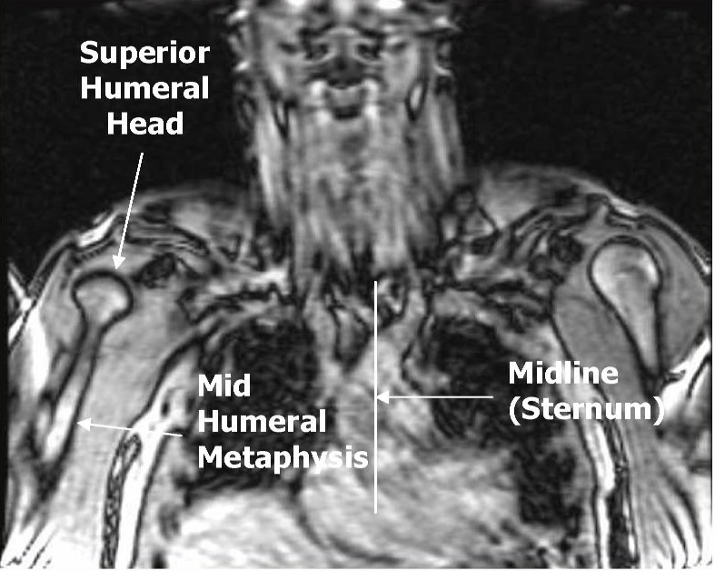
Axial and coronal Images should include sternum and humeral head.Positioning the patient prone will reduce breathing motion artifacts.


Axial Plane: Scan from superior humeral head through the xyphoid process.  The field of view should include the sternum medially, and the humeral shaft laterally.


Coronal Plane: Prescribe a plane parallel to the line from sternum through anterior humerus. Scan from skin through posterior humeral head.  Field of view should include the sternum and humerus.

Sagittal Plane: Prescribe plane perpendicular to coronal plane. Scan From sternum through lateral aspect of humerus.


SI Joint MRI Protocol


MRI SI Joint Protocol
  • COR T1
  • COR STIR
  • Axial STIR (2 STACKS)
  • Axial/Coronal PD Fat Sat
  • SAG T1
  • SAG STIR
POST CONTRAST  

  • Post gad Axial T1 Fat Sat
  • Post gad Oblique Coronal T1 Fat Sat

CORONAL IMAGING PLANE OF SI JOINTS MRI

Oblique Coronal is angled parallel to the sacrum.FOV for the coronal images should include the entire sacrum and coccyx, and both SI joints

HIP Joint MR-Arthrogram Protocol


HIP MR-ARTHROGRAM
For dedicated imaging of a single hip during arthrogram, a smaller field of view with a dedicated coil or flexible surface coil is used, allowing for visualization of smaller structures such as the labrum.  Notice the decreased SNR due to the smaller field of view.


Sequence for HIP Arthrogram


  • Coronal - both hips T1
  • Axial - affected hip      T1 Fat Sat
  • Axial -affected hip       PD Fat Sat
  • Coronal -affected hip   T1 Fat Sat
  • Coronal -affected hip PD Fat Sat COR
  • Sagittal -affected hip T1 Fat Sat SAG
  • Sagittal -affected hip PD Fat Sat SAG
  • Optional 
  • Oblique Axial T2 parallel to femoral neck


Read more regaring HIP Joint:


HIP Joint Anatomy

Hip Joint MRI Reference Lines


Axial Imaging Plane


  • Prescribe plane parallel line bisecting lesser trochanters and/or acetabular roofs. Scan from iliac crests through lesser trochanter.
  • Use COR T1 and angle parallel to femoral heads/acetabuli
  • Cover from 2-4 slices above acetabuli down close to lesser trochanters
  • Parallel Sat Bands
Coronal Imaging Plane


FOR HIGH RESOLUTION WITH FLEX COIL PLANNING


  • Prescribe plane parallel femoral heads.
  • Scan from ischium through pubicsymphyses
  • Use Axial LOC and angle parallel through femoral heads
  • Cover from back of ischial tuberosities to at least 2 slices anterior toacetabuli (preferably to cover pubic symphysis)
  • Superior Sat bands for STIR and T1
Sagittal Imaging Plane


  • Prescribe plane perpendicular to coronal plane.Scan from acetabulum through greater trochanter.
  • Perpendicular to COR PD
  • Use COR PD and cover from outer cortex of the greater trochanter to the 
  • inner portion of the acetabulum
  • Center at Femoral Head/Neck Junction
Axial Oblique Plane


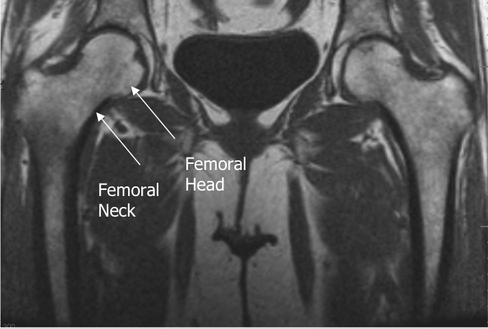
Prescribe plane parallel to femoralneck.  Scan through entire femoral neck.

  •  Use COR PD and angle parallel to femoral neck (use image with the longest medial/inferior femoral neck cortex).  This angle is usually slightly more than you think (see image).
  • Cover from 1 slice out of acetabulum superiorly to 1 slice out of 
  • acetabulum inferiorly
  • Center at Femoral Head/Neck Junction Superior Sat Ban


                                                             AXIAL OBLIQUE IMAGE-PD FSE


Read more regaring HIP Joint:


HIP Joint Anatomy


Hip Joint MRI Protocol


Magnetic resonance imaging (MRI) of hip joint - is one of the most promising and rapidly improving techniques of modern diagnostics. In this case, the doctor is able not only to investigate the structural and pathological changes, but also to assess the physico-chemical, pathophysiological processes of the hip joint as a whole or its individual structures.


MRI HIP SEQUENCES

  • COR T1 SE NON FAT SAT
  • COR FSE STIR
  • AXIAL T2 FSE FAT SAT
  • AXIAL OBLIQUE PD FSE FAT SAT
  • Axial STIR
  • COR T2 FSE FAT SAT
  • SAG PD FAT SAT

Sternum MRI Protocol


STERNUM MRI SEQUENCES


Axial T1
Axial T2
Axial STIR
Coronal T1
Coronal STIR
Sagittal T2 Fat Sat
Sagital T1 

Optional POST GAD:
Axial T1 Fat Sat
Coronal T1 Fat Sat

The sagittal plane is especially useful in evaluating the sternum and retrosternal region. Optional prone position according to the radiologists opinion is suggested. It will reduce the motion artifacts due to breathing.
Related Posts Plugin for WordPress, Blogger...

Popular Posts