
Showing posts with label Reference lines/Imaging planes. Show all posts
Showing posts with label Reference lines/Imaging planes. Show all posts
MRI Brain Reference Lines/Images
IN THIS ARTICLE:
- MRI Brain Axial Planning/Reference Lines
- MRI Brain Coronal Planning/Reference Lines
- MRI Brain Sagital Planning/Reference Lines
MRI Brain Axial Planning/Reference Lines


LOOK AT TO THE RED AC AND YELLOW PC ..
- Axial MRI Brain slices are positioned parallel to the bicommissural line,which links to the anterior and posterior commisure(yellow line).
- Axial Brain mri slices can be also position parallel to a line linking the floor of the sella turcica to the fastigium of the fourth ventricle .
- Another Axial Brain MRI refference line is,position the slices parallel to a line linking the inferior borders of the genu and splenium of the corpus callosum
These imaging planes differ by a few degress. It is important that if you are a Technologist/Radiologist set a standard imaging plane from these 3 suggestions and therefore you can compare the follow-up scans compare to the baseline study and even you can compare any of the scans performed under you.
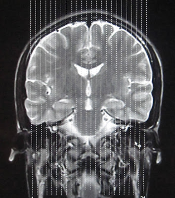
MRI Brain Coronal Planning/Reference Lines
 |
| MRI BRAIN CORONAL REFFERENCE LINE |
For CORONAL MRI BRAIN an imaging plane parallel to the brainstem is preferred in sagital blocaliser, in axial localizer the mid scan line is made parallel to the the line joining the right and left internal auditory meatus or posterior aspect of orbits. This gives symmetrical coronal images. Make sure that the scan lines cover the whole brain parenchyma from frontal lobe to the posterior aspect of cerebellum.
MRI Brain Sagital Planning/Reference Lines

Use the coronal scout to plan the true midsagittal image parallel to the falx and other midline structures.
On a true midsagittal image a line is drawn through the hypophysis and the roof of the fourth ventricle (fastigium).
This is called the HYFA: hypophysis-fastigium line.
This is called the HYFA: hypophysis-fastigium line.
The HYFA line should pass through the interhemispheric fissure in axial localizer and in coronal localizer, the scan lines are made parrallel to the interhemispheric fissure so that the sagittal images cover whole brain parenchyma from right sylvian fissure to the left sylvian fissure.


READ MORE ABOUT:
Pituitary MRI Protocol
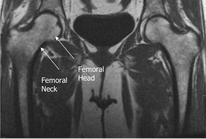
Hip Joint MRI Reference Lines

Axial Imaging Plane


- Prescribe plane parallel line bisecting lesser trochanters and/or acetabular roofs. Scan from iliac crests through lesser trochanter.
- Use COR T1 and angle parallel to femoral heads/acetabuli
- Cover from 2-4 slices above acetabuli down close to lesser trochanters
- Parallel Sat Bands


- Prescribe plane parallel femoral heads.
- Scan from ischium through pubicsymphyses
- Use Axial LOC and angle parallel through femoral heads
- Cover from back of ischial tuberosities to at least 2 slices anterior toacetabuli (preferably to cover pubic symphysis)
- Superior Sat bands for STIR and T1
Sagittal Imaging Plane


- Prescribe plane perpendicular to coronal plane.Scan from acetabulum through greater trochanter.
- Perpendicular to COR PD
- Use COR PD and cover from outer cortex of the greater trochanter to the
- inner portion of the acetabulum
- Center at Femoral Head/Neck Junction
Axial Oblique Plane


Prescribe plane parallel to femoralneck. Scan through entire femoral neck.

- Use COR PD and angle parallel to femoral neck (use image with the longest medial/inferior femoral neck cortex). This angle is usually slightly more than you think (see image).
- Cover from 1 slice out of acetabulum superiorly to 1 slice out of
- acetabulum inferiorly
- Center at Femoral Head/Neck Junction Superior Sat Ban
ELBOW MRI REFERENCE LINES
IN THIS ARTICLE:

 AXIAL
AXIAL


CORONAL REFERENCE LINE IN MRI PLANNING


SAGITAL REFERENCE LINE IN MRI PLANNING
 Photograph shows patient positioning for flexed abducted supinated view: patient is positioned prone on MRI table with elbow in flexed abducted supinated view position. Notice position of arm, flexed at elbow and abducted at shoulder with supinated forearm, thumb up.
In general, it was preferable for the patient to lie prone for these views. The shoulder was abducted 180°, with the arm beside the head. The elbow was flexed to 90°, with the forearm supinated, thumb up, and a shoulder phased array coil was placed around the elbow . The position is referred to in this article as the flexed abducted supinated view, but usually in our practice it is termed the “FABS view,” meaning the flexed elbow with the shoulder abducted and the forearm in supination view.

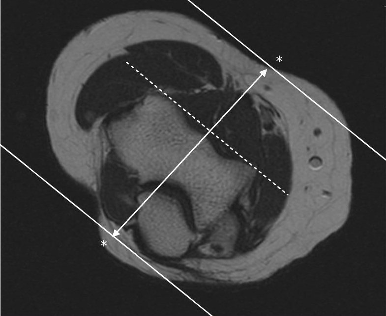
Localizer MR image with lines shows slice positioning for flexed abducted supinated view. Notice sections, sagittal to long axis of body but coronal to anatomy at elbow. Ideal angulation is planned along distal biceps brachii tendon, but often, as here, this structure is not clearly visible on localizer images. In this case, sections nearly perpendicular to radius provide reasonable and reproducible imaging plane.
 Coronal T1
Coronal T1 and PD fat suppressed sequence are well suited for evaluation of collateral ligament and common extensor/flexor tendon group patholgy as well as epicondylitis.
 COR PD FAT SAT
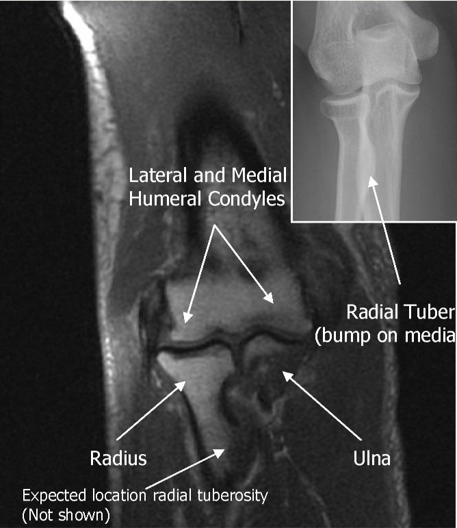
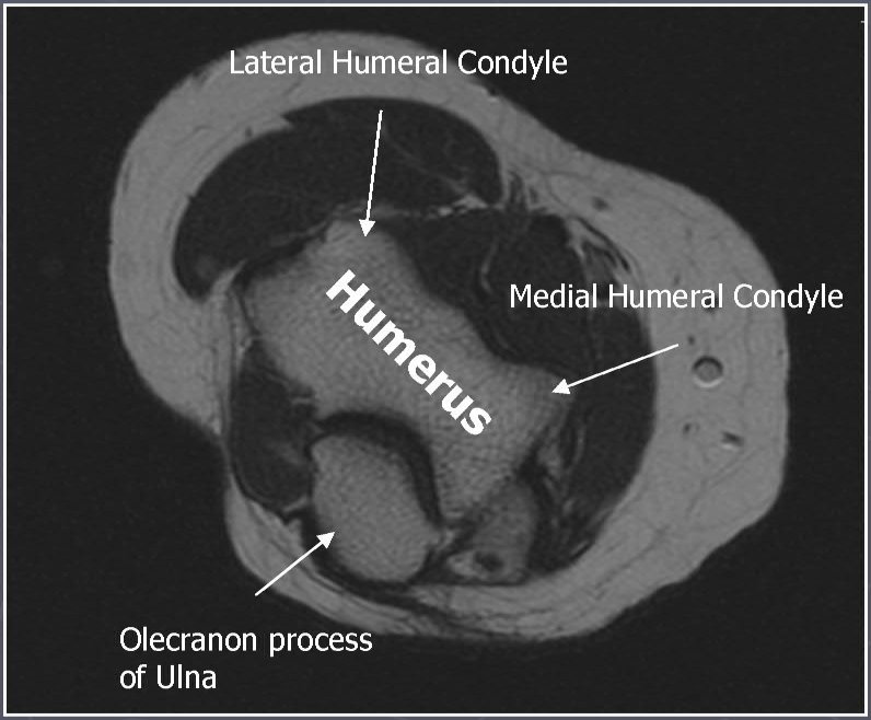
 AXIAL T1
Axial T1 and PD FSE fat suppressed sequences evaluate the tendons of the Biceps Brachii and Brachiallis muscles transversely as they insert onto the Radius and Ulna respectively. The distal Triceps tendon is also well evlauated in this plane.
 AXIAL PD FAT SAT
 T1 SAG
Sagittal T1 and PD FSE fat sat sequences evaluate the tendons of the Biceps Brachii and Brachiallis muscles as they travel distally to instert onto the Radius and Ulna respectively. They also help evaluate the Radial head for radiographically occult fractures. The distal Triceps tendon is also well evlauated in this plane.
 PD FAT SAT SAG
 ELBOW ARTHROGRAM
Coronal T1 fat saturated arthrogram is useful for evaluation of the collateral ligaments and cartilage surfaces.
READ MORE ABOUT:
MRI ELBOW PROTOCOL
- AXIAL REFERENCE LINE
- CORONAL REFERENCE LINE
- SAGITAL REFERENCE LINE

AXIAL REFERENCE LINE- Perpendicular to Coronal
Use COR to angle parallel to elbow joint (parallel to capitellum and trochlea),Cover from 1 slice distal to radial tuberosity up as far as the slices go. Parallel Sat Bands (above and below)
CORONAL REFERENCE LINE
Use axial LOC to angle parallel to anterior portions of the capitellum and
trochlea (or parallel to humeral epicondyles)
Use sagittal LOC to angle parallel to humerus/radius/ulnar plane, but
closer to plane of radius if minimally flexed (if markedly flexed elbow,
then angle between anterior humerus and the radius)
SAGITAL REFERENCE LINE
Perpendicular to both Coronal and Axial sequences,Cover 1 slice outside of both humeral epicondyles
AXIAL REFERENCE LINE IN MRI PLANNING
AXIAL

AXIAL REFERENCE LINES


CORONAL ELBOW REFERENCE LINES


FABS VIEW
In general, it was preferable for the patient to lie prone for these views. The shoulder was abducted 180°, with the arm beside the head. The elbow was flexed to 90°, with the forearm supinated, thumb up, and a shoulder phased array coil was placed around the elbow . The position is referred to in this article as the flexed abducted supinated view, but usually in our practice it is termed the “FABS view,” meaning the flexed elbow with the shoulder abducted and the forearm in supination view.
Localizer MR image with lines shows slice positioning for flexed abducted supinated view. Notice sections, sagittal to long axis of body but coronal to anatomy at elbow. Ideal angulation is planned along distal biceps brachii tendon, but often, as here, this structure is not clearly visible on localizer images. In this case, sections nearly perpendicular to radius provide reasonable and reproducible imaging plane.
Coronal T1Coronal T1 and PD fat suppressed sequence are well suited for evaluation of collateral ligament and common extensor/flexor tendon group patholgy as well as epicondylitis.
COR PD FAT SATAXIAL T1Axial T1 and PD FSE fat suppressed sequences evaluate the tendons of the Biceps Brachii and Brachiallis muscles transversely as they insert onto the Radius and Ulna respectively. The distal Triceps tendon is also well evlauated in this plane.
AXIAL PD FAT SATT1 SAGSagittal T1 and PD FSE fat sat sequences evaluate the tendons of the Biceps Brachii and Brachiallis muscles as they travel distally to instert onto the Radius and Ulna respectively. They also help evaluate the Radial head for radiographically occult fractures. The distal Triceps tendon is also well evlauated in this plane.
PD FAT SAT SAGELBOW ARTHROGRAMCoronal T1 fat saturated arthrogram is useful for evaluation of the collateral ligaments and cartilage surfaces.
READ MORE ABOUT:
MRI ELBOW PROTOCOL
ANKLE MRI IMAGING PLANES
ANKLE AXIAL IMAGING PLANE
Axial ankle mri planning/referrence plane is parallel to axis of calcaneus.
Technical notes:
Scan ankle from distal tibia through subcutaneous soft tissues (include plantar fascia).
Cover from inferior cortex of the fifth metatarsal and cover up as far as possible ( approx. five slices above the tibiotalar joint)
Parallel Sat Bands
Cover from 3-4 Slices above the inferior margin of the tibiotalar joint (the
joint is best seen posteriorly) down as far as the slices go


ANKLE SAGITAL REFERENCE LINES-PLANNING
Prescribe plane with line parallel to talus, angled perpendicular to talar dome. Perpendicular to COR
Technical notes:
Cover ankle from medial through lateral malleolus.
Angled perpendicular to talar dome
Cover at least 1 slice out of both malleoli
All of the plantar soft tissues should be included in the FOV
Superior Sat Band


ANKLE CORONAL REFERENCE IMAGES-PLANNING
Prescribe plane perpendicular to axial imaging plane. Use axial LOC and angle perpendicular to the inner cortex of the medial malleolus
Technical notes:
- Scan ankle from calcaneus through metatarsal bases.
- Use sagittal LOC and angle parallel to distal tibial shaft and cover from the talonavicular joint to at least 2 slices posterior to the talus
- The COR PD FS sequence is thicker and can cover more of the talonavicular joint anteriorly and plantar fascia posteriorly
- All of the plantar(inferior) soft tissues should be included in the FOV
- Superior Sat Band


Ankle tendons and ligaments are best imaged with the foot plantar flexed 15-30°. So don't use the chimney in the coil. Position the calcaneus in the middle of the coil and the relaxed foot will fit comfortably in the coil at the correct degree of plantar flexion.


 T1 SAGITAL
 SAGITAL IR
Sagittal T1 and IR allow for the evaluation of the Achilles tendon, plantar aponeurosis, talar dome, subtalar facets and Sinus Tarsi.
 AXIAL PD FAT SAT FSE
Axial PD fat suppression evaluates the tendons and ligaments of the ankle particularly after acute/subacute injuries. It also is sensitive to talar dome osteochondral defects. Alternatively, a T2 sequence can be used to eliminate magic angle artifact that may occur as the tendons travel around the malleolar turns
 COR OBLIQUE T1
The coronal oblique T1 sequence follows the tendons of the ankle around the malleolar turns and also evaluates the medial ankle ligaments.
 COR PD FSE FAT SAT
The coronal oblique PD fat suppressed sequence follows the tendons of the ankle around the malleolar turns and is particularly important in evaluation of the Posterior tibialis tendon.
Ankle MR Arthrogram


 Arthrogram sequences of the ankle evaluate the talar cartilage and allow for staging of ostechondral defects of the talar dome. They can also better evaluate the joint capsule and its boundaries such as the anterior talofibular ligament
Coronal T1 spin echo (SE)
 General anatomic assessment of the ankle. The tibiotalar articulation, as well as the tibiotalar ligaments are assessed. Assessment of the bone marrow on T1 is important also.
Axial T1 spin echo (SE)

Ankle tendons, muscles, general ankle anatomy all re-evaluated with this sequence. Assessment of the bone marrow on T1 is important as mentioned above.
Axial STIR

This sequence is the best to screen the bones to make sure there is not a subtle bone edema or fluid collections that is not visible on other sequences.
Subscribe to:
Posts (Atom)

Popular Posts
-
Normal and a rupture Achilles tendon MRI images Achilles tendon MRI image-yellow arrow Green-normal Achilles tendon MRI image ...
-
Axial Plane: Prescribe plane perpendicular to midshaft of the proximal phalanx of the thumb. Scan from 1st carp-metacarpal joint th...
-
Early identification of ischemic stroke: diffusion restriction may be seen within minutes following the onset of ischemia Correlates wel...
-
Normal MRI Anatomy The pectoralis tendon is best seen on axial T1 and T2-weighted images as a curvilinear low-signal band inserting o...
-
 --> Routine shoulder protocols are the most variable, but most include SHOULDER MRI SEQUENCES ...
 -
Prostrate MRI Appearence T1‐weighted MR images, the normal prostate gland demonstrates homogeneous intermediate to‐ low signal inten...
-
The sternum and sternoclavicular joints are difficult to evaluate with plain radiographs. The value of CT in assessing lesions of the...


